
We’ll start by considering the sum of the moments about point A which must equal zero. So consider the simple Warren truss below subject to point loads at nodes B and D.Īs with any statically determinate analysis, the first task is to determine the support reactions. The key thing to remember with the method of sections is that our plane cannot cut through more than three members with unknown member forces.Īs usual, the best way to understand this technique is by working through an example. So we now have three equations of statics at our disposal.

Since the structure is in a state of static equilibrium, the sum of the moments (just like the forces) must equal zero. This method of structural analysis brings into play a third equilibrium equation because all of the forces acting on the sub-structure no longer all pass through the same point, we can now consider the sum of the moments about any point which, is our third equation. We can then evaluate equilibrium of either of the two sub-structures created by the cut. In doing so, we reveal the internal member forces in the members our plane cuts through.

Instead of isolating a single joint, the method of sections involves us making an imaginary cut through the entire structure. Now we can consider the other tool at our disposal, the method of sections. We’ll see this in action again a little later! 3.0 Method of Sections Truss Analysis As long as you can identify a node within your truss structure that has no more than two unknown member forces passing through the node, you can deploy the joint resolution method. We’ve only demonstrated it so far for a very simple truss but the process is exactly the same no matter how big your truss gets. That’s the joint resolution method in a nutshell. This can initially be counter-intuitive so make sure you’re happy with this convention before proceeding, otherwise you’ll get terribly confused later on. By the same analogy, the force arrows for member BC point inwards as if to resist a force trying to pull apart or stretch the bar.
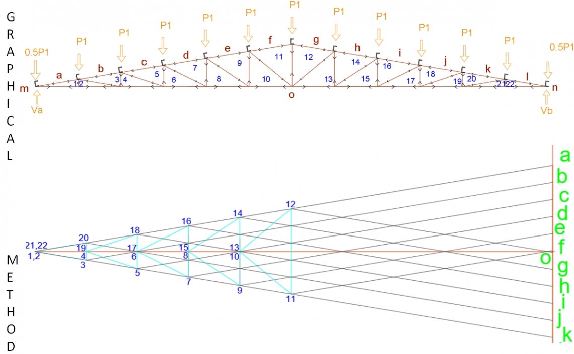
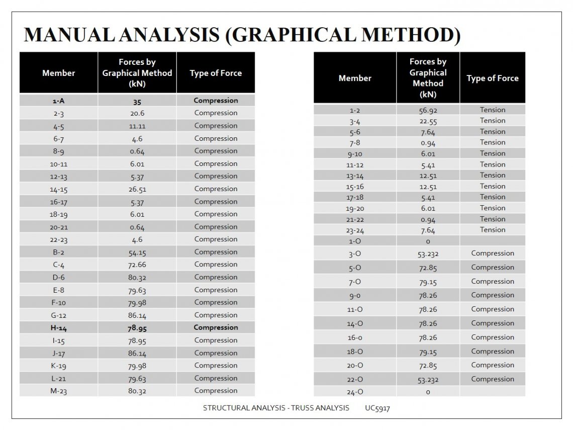
GRAPHICAL METHOD OF TRUSS ANALYSIS PDF FREE
Consider the two bar truss again, shown below as a free body diagram.įree body diagram of joint A showing internal member forces (the load path).įor member AB in compression, the yellow force arrows point outward, as if to resist a force compressing the member. We’ll start by considering the joint resolution method which involves evaluating force equilibrium at each joint or node and using the equations of statics to solve for the unknown member forces. Only then can we employ the joint resolution method, method of sections or a combination of both. In both cases, we must first determine the support reactions for the structure. We’ll focus on two similar techniques that make use of the equations of static equilibrium. In other words we want to be able to work out the forces developed in each of the members in response to external loading.

GRAPHICAL METHOD OF TRUSS ANALYSIS PDF HOW TO
Now that we’ve clarified what a truss is and the concept of a load path describing the transmission of forces through the structure, the next task is to work out how to identify the forces along the load path. 2.0 Joint Resolution Method of Truss Analysis Simple 2-bar truss subject to a single externally applied force (left) and resulting load path (right). Take the simplest form of truss as an example. To fully understand the assumptions inherent in our truss analysis techniques discussed below, make sure to read this post.įrom an engineering perspective, a truss, like any structure has one purpose, to transmit externally applied forces through the structure and back into the supports or foundations of that structure. ⚠️ I’ve covered the differences between theoretical and actual truss behaviour in this post. Only forces can be transmitted through nodes. As such, moments cannot be transmitted from one member into adjacent members. This means that the members meeting at a node are free to rotate relative to each other. 1.1 Theoretical truss behaviour and load pathsĪs we’ve said, theoretically at least, all truss nodes are effectively pins or hinges. The individual structural members in the crane could be reasonably modelled as axially loaded truss elements. The tower crane is a great example of a truss structure used to efficiently transmit large loads.


 0 kommentar(er)
